This is the multi-page printable view of this section.
Click here to print.
Return to the regular view of this page.
Concepts
This section covers the basic concepts of using Vixen.
Overview
Vixen is quite a paradigm shift from the legacy sequencers in the way the lighting concepts come together. In other software(including Vixen 2.x), it’s normally a case of setting up your controllers, and then you have a list of numbered outputs that you can use to sequence on; that is, you’re sequencing directly against the outputs/channels for the controller. However, in Vixen, these ideas have been broken down into two distinct areas: the physical components of your display (ie. the controllers and their outputs), and the logical or abstract components of your display (eg. the items or props or fixtures that you have). Additionally, because the design has been broken into these two parts, there’s another important component to it: how they actually connect up (eg. how the items/fixtures relate to the controllers and outputs). These three components are called Controllers and Outputs (for the physical components); Elements and Groups (for the logical or abstract components); and Patching (to define how elements are connected to Controllers/Outputs).
1 - Display Elements and Groups
Overview
Elements are the building blocks to modeling a Prop in Vixen 3. The purpose is to be able to model how a display is set up, and not be concerned with the physical realities of the hardware, controllers, channel numbers, etc. To assist in this, elements can be nested into groups to associate common elements to model a physical Prop. These groups are critical for some of the advanced sequencing tools, later on.
The general intent for the development and creation of elements is that it should represent or model something in your display. (e.g. an item, or fixture, or prop) If you have elements that you’re naming things like Renard-37, Channel-21, Tree-1-Red lights, then you’re going about it the wrong way.
Elements are the entry point for data into the Vixen system. For example, when sequencing a song, the user would sequence data against the elements and groups in their configuration. When playing back the sequence, the effect is applied to one or a group of elements and then it is processed through to the to the appropriate controller in a way that abstracts the details from the user.
Example
For example, a Megatree item in a display might be defined as a group called Megatree, with 16 elements inside it: Megatree-1 through to Megatree-16 that represent the 16 strings of lights around the tree. If those strings are pixels, then there might be 50 other elements nested within each string that represent each pixel. Or, a display might have multiple shrubs/bushes around a garden: 4 on the left, 8 in the middle, and 4 on the right. A user might decide to group each set of shrubs into one group (eg. Shrubs-Left, Shrubs-Middle, Shrubs-Right), and then group those 3 into another group called Shrubs. This allows effects to be used on all shrubs or just one area very easily. The idea is to apply effects at the highest level items that represent things we know, not the elements of the physical lights.
Properties
Elements and groups also have the ability for extra Properties to be defined and configured for each element or group. The intent of a Property is to give the user some way to provide extra information about that element in the display. This information will be used by the effects in the sequences. A color handling property can be used to restrict effects on that element to a certain range of colors. Or, a Position property, can represent the position of elements in their display. Some of these are configured by the user on setup, and others get created as part of another setup process. The Position properties are generally set automatically by the preview when it is configured and based on the location of elements in relation to each other.
2 - Color and Brightness
Overview
Color and brightness are handled a bit differently in Vixen 3. To understand the color system in Vixen 3, you need to know a little bit about color models.
RGB (Red Green Blue)
The RGB (Red, Green, Blue) color model is the most well known and is what is used most commonly in other sequencers. It defines a color space in terms of three components:
- Red, which ranges from 0-255
- Green, which ranges from 0-255
- Blue, which ranges from 0-255
The RGB color model is an additive one. In other words, Red, Green and Blue values (known as the three primary colors) are combined to reproduce other colors. For example, the color “Red” can be represented as [R=255, G=0, B=0], “Violet” as [R=238, G=130, B=238], etc.
Its common graphic representation is the following image:

HSB (HSV) color space
The HSB (Hue, Saturation, Brightness) color model defines a color space in terms of three constituent components:
- Hue : the color type (such as red, blue, or yellow).
- Ranges from 0 to 360° in most applications. (each value corresponds to one color : 0 is red, 45 is a shade of orange and 55 is a shade of yellow).
- Saturation : the intensity of the color.
- Ranges from 0 to 100% (0 means no color, that is a shade of grey between black and white; 100 means intense color).
Also sometimes called the ‘purity’ by analogy to the colorimetric quantities excitation purity.
- Brightness (or Value) : the brightness of the color.
- Ranges from 0 to 100% (0 is always black; depending on the saturation, 100 is the brightest version of the color in the given hue and saturation.).
Its common graphic representation is the following image:

The HSB model is also known as HSV (Hue, Saturation, Value) model. The HSV model was created in 1978 by Alvy Ray Smith. It is a nonlinear transformation of the RGB color space. In other words, color is not defined as a simple combination (addition/substraction) of primary colors but as a mathematical transformation.
Note: HSV and HSB are the same, but HSL is different. HSL and other color models are beyond the scope of this document and will not be explained here.
Color Models and Light Sequencers
As mentioned earlier, most sequencers other than Vixen 3 use the RGB color model. While this corresponds conveniently with most basic RGB lighting devices, it’s not particularly convenient for actually working with color and brightness transitions in lighting design. For lighting applications, the HSV color model is a more suitable system for conceptually working with color and brightness. It is actually more useful to think about color and to interact with it using the parameters of the HSV system. For example, in the RGB color model, if you wanted to make the lights brighter, you would have to take all three values and increase them proportionally. In the HSV model, you would just increase the V value. Similarly, if you want to make a color more or less vibrant, you would increase or decrease the saturation.
Of the 3 parts of a HSV color, only two parts describe the color: the Hue and Saturation. The Value describes how bright the color is. In vixen 3, the Hue and Saturation are controlled by the color controls (color picker or gradient editor). This describes the color itself. The Value is always tied to the brightness controls (intensity or curve). This is how bright the light is.
You’ll notice in the color picker, that the V is always 100. You can only choose the full brightness version of any given color. This is often a point of confusion with users who are used to other sequencers. If you want to adjust the intensity, you don’t use the color picker. That is done using the intensity controls. For example, if you wanted to create a dark green color, you might be familiar with using like RGB values 17, 130, 41. This translates to a Hue of 133, Saturation of 87 and a Value of 51. The value will always be 100 on the Vixen 3 color picker. Vixen will automatically correct this to 100, and you will see your RGB values change to 33, 255, 80. This looks like a bright green. There’s nothing wrong here, this is how it is designed to work. To get that dark green, you then need to set the intensity (or curve, depending on the effect) to 51.
Colors and Gradients
The word Color is used to refer to a color that doesn’t change over time. Colors that change over time are referred to as Gradients. Gradients contain one or more colors, and the timing relationship of when the colors change. The time relationship is not absolute. It is a percentage relative to the length of the effect.
Intensity and Curves
Similar to the concept of colors and gradients above; an intensity is a fixed brightness value. A Curve is a change in brightness over time. The time relationship is not absolute. It is a percentage relative to the length of the effect.
*Color model explanations and imagery from colorizer.org.
3 - Element Color Types
Overview
It’s a common misconception that Vixen 3 is for RGB (Pixel) lights. It is true that it’s very easy to sequence RGB lights in Vixen 3, but it’s also a great sequencer for standard Christmas lights as well. When creating your elements, you’ll need to define what kind of lights that element consists of. If you don’t configure the Color Handling, which creates the color properties, that element is assumed to be full RGB. The different types of lights are as follows:
Single Color (Discrete Color)
A single color string is usually a traditional strand of single color Christmas lights. It could also be a floodlight, or other special light that can only be one color. When configuring the Color handling for an element, you’ll need to choose what color that light actually is.
When creating effects for a single color element, you will only be able to choose the one specific color that you’ve defined for this element. They will be shown in the timeline in this color. They will also appear in this color in the preview. Generally the Basic Effects category will be the effects used on these types of elements.
Multiple Independent Colors (Discrete colors)
This is a way to use multiple single color channels as one element. This is commonly used for mini-trees or super strings made from multiple strands of single color lights where each colored string is plugged into a different controller channel. If you have an element that consists of a string of red lights, a string of green lights, and a string of white lights, this is the appropriate option to choose. This differs from RGB in that the colors don’t actually mix. If you turn on red and green, you wouldn’t see yellow, you would see red and green. When choosing this option, you’ll need to define what colors the individual lights are for this element.
Whenever you are selecting colors for basic effects on an element defined as multiple independent colors, you will only be able to choose the colors that this device supports. You may chose more than one color at a time. You will see the effect in the timeline with the separate colors you chose, they will not appear as mixed colors. In the preview, these elements will appear as separate side by side strings for each color. Generally the Basic Effects category will be the effects used on these types of elements.
RGB (Full Color)
This is used for a light that has multiple color components which mix to form secondary colors. This can be pixels, dumb RGB strings, RGB floodlights or similar devices. An RGB device is a full color-mixing device. Unlike the discrete color option, if you turn on the red and green channel, you will see yellow.
When selecting colors for effects on RGB type elements, you will be able to choose any color and it will be shown in the timeline as that color. These elements will render in full color in the preview. This opens the door to the Pixel Categories of effects.
4 - Color Gradients
Overview
Color gradients are a way of representing color over time in Vixen. Instead of having a single color, you can create colors with transitions in them that shift from one color to another. Multiple colors can be included in a gradient and you can shape via the editor the points which the colors transition from one to another. Many of the effects are then able to take advantage of this and provide features that change the color over time.
Color Points
Each Color Gradient will have one or more color points. Each color point defines what the color is at a point within the gradient. Color Gradients with more than one color point will have a transistion zone between the color points where the gradient moves from one color to the other. In between the colors there is a weighting point. When the weight point is in the middle of the two colors they will transition evenly. But if it is moved toward one color or the other, the weight of the transition will shift to favor the color the point is closest to.
Editor
The Color Gradient editor allows you to edit the color and color points in a gradient. Within the editor you can add color points and set where they lie. You can adjust the weight between them with the location dot. A simple interface into the library is available to save and load gradients. Library gradients can be edited by loading them from the library.
Library
Color Gradients may be named and saved to a library so they can be reused without havign to recreate them each time.
5 - Controllers
Overview
Controllers are the actual objects that send data out of the computer, in a specific format and transport method to real hardware in your yard. After you’ve defined your elements on a high level, you’ll need to set up at least one controller to output data to the real world. You’ll need one controller for each output of your computer. There are different kinds of controller modules that correspond with real world hardware. For example, the “Open DMX Output” controller will output one universe of DMX data using the protocol designed for the Enttec Open DMX based hardware dongle.
Configuration
When you configure a controller, you need to first specify the type. There are several supported output types that correspond with various real world hardware. After defining the controller, you need to tell it how many channels it will have. This needs to be the sum of all of the individual output channels of all actual devices connected to that port. Most controllers also have some other information specific to that device that also needs to be defined. For a Renard, it would be the Com Port, and Baud Rate; for sACN, it’s the universes and addressing. Some controller types have no configurable parameters, the Open DMX Output is one example. It doesn’t use a com port, and it has a fixed output size of 512 channels.
One common mistake is for users to define multiple controllers when you should only be using one. Many hardware systems use a common data bus where data leaves the computer from one port and then travels down a data wire in and out of several controllers in a daisy chain configuration. The Renard protocol is a good example of this. If you have a chain of Renards (regardless of type) that all connect to a computer at a single port, you need to define only one controller for that whole chain. DMX, sACN, ArtNet are also common examples of controllers that share a data bus.
On the other hand, if you have two Renard (or DMX, etc) wires connected to different ports on your computer, you need to define one controller for each data connection. Each may have it’s own number of channels, and own configuration parameters (baud rate, etc).
While it’s beyond the scope of this article, it’s important to note that some hardware supports multiple protocols. For example, a Renard controller may be configured to run DMX firmware. In that case it’s a DMX device and needs to be configured using a DMX controller, not a Renard controller.
Similarly, there are protocol converters out there that convert from one protocol to another. For example, the sACN to DMX/Renard bridge will take data in on the sACN protocol via ethernet, and convert and output that data in Renard or DMX formats. In this case, you would need to define the controller as a sACN controller in Vixen. Vixen doesn’t care what happens to the data downstream once it leaves the computer.
Another common mistake is to configure all the channels your controller can technically handle. This occurs with e1.31 controllers that can support thousands of channels. If you are only using 500 channels of the 2000 your controller supports, you only need to configure the 500 channels in Vixen. You can always change the count later on as your display expands.
6 - Curves
Overview
Curves are a way to represent change over time. There are many uses for Curves in Vixen from controlling the dimming of the outputs to how parameters change over time in the effects.
Editor
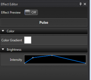
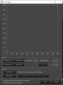
The curve editor allows you to define how a parameter changes over time. The most common place you see curves is for intensity. The Pulse effect is a key example where this is used. To create a ramp effect, the curve will be a diagonal line from the lower left to the upper right. To create a ramp down, the curve is reversed. Additional points can be added to the curve to change how it acts. The points can be dragged to the proper place, or the actual values can be edited.
Curves can also be used for non-intensity parameters as well. One example of this is the movement curve in the Chase Effect. In this case, the curve defines the motion of the chase where the Y axis represents the chase position over the Z axis which is relative time.
Once you are happy with a custom curve, you can save it to a the library and link it to other effects so they can look the same. The curve library can be edited from within the effect editor or from the Tools menu in the main sequencer window.
Since the 3.4 releases the curves can now be edited directly in the effect editor without needing to launch the full dialog curve editor. Basic adjustments can be made here to quickly shape a curve. If needed final adjustments can then be made in the full dialog editor. See Effect Editor
The full curve editor supports many features. There are buttons to reverse a curve, invert a curve, free hand draw and use a mathematical function to generate one. There are also key mouse combinations that allow a curve to be adjusted. Holding the Shift Key and click dragging a point on the line will convert it to a flat line curve. It can be freely moved up and down to any point on the graph. This mimics functionality in the inline curve editor.
Curve Library
The Curve library can be accessed in several ways from the Sequence Editor.
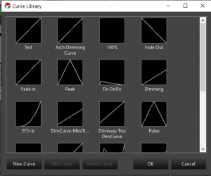
- Tools -> Curve Editor This bring up a dialog window with the Curve library and allows new curves to be added and existing ones to be edited or deleted.
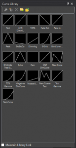
- View -> Curve Library Window This opens a docking window that can be placed in docked locations in the editor. This allows the same features as above, but you can also drag them out and drop them on effects. You can also import/export the library to share between profiles or others.
- Toolbar By right clicking in the toolbar you can add other toolbars such as the curve library. The toolbar has the same features as the docker window. The features can be accessed by right clicking on the toolbar to bring up the menu.
7 - Filters and Patching
Overview
Patching is the idea used to tell Vixen how a element relates to an output. In a simple setup, a user might have 12 mini-trees, and a single Renard to control them. They might patch each mini-tree channel directly 1:1 to a corresponding output on the Renard. This is a simple use case, and is the equivalent to the way Vixen 2.x works: a direct 1:1 correlation between elements that the user sequences with and the outputs from the controller.
However, in a more complicated setup, there may not be 1:1 mappings. For example, say the user has a large tree that has been wrapped in 8 strings of lights, and they have each string on a different output on a controller. If they wanted to treat the tree as one single object (eg. not control each string individually), they can map the one “Tree” element to the 8 controller outputs that correspond to the strings.
Filters
In this patching system we have also introduced the concept of ‘filters’ which can be inserted in the path from elements to controller outputs. Filters are intended to take data in, manipulate it in some way, and then output the data. For example, a simple filter might be a dimming curve. The Dimming Curve filter has a single input and a single output. It transforms the intensity value of any lighting data it gets according to a user-configured curve. It wouldn’t affect the data in any other way, or doesn’t distinguish between multiple pieces of data coming in: for example, if there are two lighting values that come in at the same time, it transforms them independently, then outputs the two lighting values.
A more complex filter might be the Color Breakdown filter. This can be configured to take any given lighting value, and split up the data based on the color component of the lighting value. It will then output the broken-down values on independent filter outputs. For example, a common example would be an RGB breakdown filter. The filter would be configured with 3 components: pure red, green and blue and when it gets a lighting value, it would split it up into the red part, green part, and blue part, and output those (component) lighting values on the 3 filter outputs.
Filters can also be stacked, so you could have a dimming curve (to adjust the intensity of all data), which then goes through a color breakdown filter to split it out suitable for a particular controller scheme.
Finally, there are other possibilities for filters that haven’t yet been implemented: for example, some DMX systems might control a movable lighting fixture with a 16-bit value for a movement axis. However, since DMX is 8-bits per channel, it combines two for the full 16 bits. A filter might be created which takes in a generic “movement” data item, and splits it into a 16-bit value, but on two separate outputs (for the high 8 bits and the low 8 bits). These might then be patched to the appropriate DMX channel.
One current limitation of the patching/filtering system is that any component, filter or outputs, can only have a single source item. That is, you can’t patch two different channels to a single output. This is scheduled to be changed, but is probably not that common a use case, so it may be a while until we get to it.
8 - Streaming ACN
Overview
Streaming ACN, also known by it’s abbreviation sACN or by its technical specification document number e1.31 is a lighting protocol that encapsulates DMX type data and sends it over a TCP/IP Ethernet network. It is an intermediate step between DMX based lighting controls, and full ACN based implementations. ACN (Architecture for Control Networks) is an extensible suite of protocols that can be used to control all varieties of devices used in live production networks. Since a full transition to ACN is a major paradigm shift, sACN was created that operates within an ACN network and uses familiar concepts from the DMX standard that has been in common use for decades. DMX defined the electrical signaling as well as the data format. Only the concepts of channels and universe and a loose guideline for timing is carried forward from DMX to sACN.
Universes and Channels
In DMX, only 512 channels of data could be carried on a DMX cable. This was a limit based on the balance of data rate, distance requirements, multidrop topology and refresh rate. With all of those factors considered, 512 channels was defined as the standard number of channels in a universe. As shows grew, and designers needed more than 512 channels to control a show, it became necessary to implement multiple independent DMX networks. While not part of the standard, the term universe became the standard term to refer to each separate DMX network. In the DMX world, every group of 512 channels was its own physical network and this network was called a universe.
Ethernet networking has far greater capacity for bandwidth and routing. In fact, the bandwidth of the network has no defined limit in Ethernet networking. Faster and faster links continue to be invented and come into common use. Ten years ago, 100BaseT was common. Now 1000BaseT and even 10GBaseT are becoming more and more common. So there is no need to limit the number of channels transmitted on an Ethernet network. However, to maintain backwards compatibility, and to make it easy for hardware developers to implement new transitional devices, the 512 channel per universe limit was kept. But you can now send many universes on the same wire. sACN currently allows 63,999 universes on a network. This doesn’t mean this will work on a 10Mbps network. But you can get pretty close on a 1000Mbps network.
Addressing
Many people get tripped up over Universe/Channel addressing. It’s actually quite simple. Channels are grouped into universes and universes are numbered. You can think of it similar to postal addresses. The channel is like the house number, and the universe is like the street name. You can have a 101 First street, and a 101 Second street and the proper mail will get to the right houses.
A universe can have any number of channels in it from 1 to 512. But each universe always starts at channel 1. If you only have 50 channels to send, you can have a universe send only channels 1-50. But you cannot send only 51-100. (why would you want to?)
Why do I see the number 510 or 170?
Pixels or RGB elements take 3 channels to communicate the data for the Red, Green and Blue parts of the color. If you have 10 pixels, you need 30 channels.
512 does not evenly divide by 3. 512 = 170 1/3. So you can only fit 170 full pixels into a universe with 2 channels left over. 510 channels is 170 pixels worth of data. Earlier models of pixel controllers did not bridge this gap across universes and required you to contain full pixels within a universe. This is becoming less common on newer hardware designs. It’s important to know which universe size your hardware supports when configuring the sACN universe outputs.
Multicast Vs Unicast
ACN is designed to be a minimal configuration control protocol. It is intended that the show controller (the computer) just puts the data out onto the network, and the receivers see everything and get configured to use only what they need. For this reason, multicast networking makes the most sense. Multicast is a mechanism where the sender transmits the data, and the receivers see the available data and use it.
Multicast is a network assisted technology that relies on the network to manage which devices want the information and which don’t care. It is backwards compatible with networks that have no specific multicast support. But in these environments, since there is no assistance at the network level, every device gets all of the data. This can easily result in a network that gets very congested. It also tends to overwhelm many simple hardware receivers because they must inspect each packet of data to determine if it should use it or not.
This network guided delivery of data relies on a standard networking protocol called IGMP (Internet Group Management Protocol). This is a system where listeners who are interested in a stream will subscribe to the group. The switches then forward the traffic to only the switch ports where there are subscribers. In the context of sACN, the groups correspond with a particular universe. For this to work, you need network switches and routers that support multicast routing and/or IGMP snooping. In general this is not a feature found on home networking equipment. It’s found on managed or smart switches.
Because many people use low end networking equipment, especially in the early days of sACN adoption, The sACN standard also allows for unicast transmission of the data. Basically, the standard says that while multicast is preferred, receivers must process any data that gets to it. This helps to reduce network flooding on networks without proper multicast support.
It’s a myth that you can send more universes using unicast than you can by multicast. When the network is doing its job, and all devices are following the rules, the traffic is the same in both cases. It can even be less with multicast, because if more than one controller is getting the same universe data, only one packet is sent to the whole network, not one per device. The unicast is better myth started in the DIY Christmas Lighting hobby. The early model pixel controllers didn’t properly implement IGMP subscriptions, so it looked like it didn’t work anyhow. And these same devices had to employ other means to cope with the overload of data coming in the ports. So there were artificial restrictions placed on it that were safe amounts of data the controller could handle without overload.
sACN over WiFi
When using WiFi as a link for your sACN data, multicast is always better because of the physical nature of wifi being a broadcast medium. There’s no magical network switching happening in mid air. Multicast also bypasses certain physical layer data integrity checks in 802.11 WiFi. WiFi makes assumptions in the fundamental design that it’s more important for data to arrive without errors than it is for it to arrive on time. While that’s true for most general purpose internet traffic, that’s not the case for live show realtime data. For our applications, its more important that the data arrive on time, than arrive correct. If it had to retry because there were data errors, it would be too late anyhow. So it’s better that data gets dropped than for it to arrive late. That’s what happens in multicast over WiFi. Unicast on the other hand will retry a few times until it knows the receiving device got the data and got it correctly. This will usually be seen as irregularly lagging transitions on your lights.
Optimizing the stream
While the specification doesn’t give a hard and fast timing for how often a universe should be refreshed, it will never be more than 44 times per second, which is the maximum speed allowed in the old DMX standard. It is typically much lower though - often corresponding on the frame rate of your sequencing or lighting software. Vixen 3 defaults at a 50ms interval which corresponds to 20 frames per second. Like DMX, sACN is designed to be a streaming format where all the data keeps getting resent over and over regardless of whether it’s changed. If a light didn’t get the message right the first time, it’ll have another chance 50 milliseconds later.
In contrast, if you’re familiar with Light O Rama, you may have experienced stuck effects. LOR is not a streaming format. It’s a state change protocol. It sends instructional commands that tell the lights what to do over what period of time. If one message is missed, the light doesn’t change. DMX (and sACN) do not have this problem because they keep repeating what all lights should be doing at every given moment.
But you can probably imagine, that sending the same data over and over ad infinitum is a whole lot of unnecessary data. Especially when you consider that many lights aren’t changing for reasonable periods of time even in an active show. As mentioned earlier, there’s no minimum refresh timing in sACN. The specification further gives the receiving device the discretion to determine what duration means that there’s no more data coming and the source is inactive. Though it’s generally accepted that you should get at least one frame of data per minute for the source to be considered alive. Furthermore, the specification allows the receiving device to decide what to do when it determines that there’s no active data. It could shut everything off, or turn it on to a predetermined level, or execute some internal program. Or it could leave everything at the level it was last set.
You probably get the comments that you must have a high electric bill with all those lights. But you probably also know that by blinking the lights, they’re off more than they’re on and the electric bill isn’t that bad. The same line of thought follows with the network traffic. If you’re going a few seconds at a time without changing a value, why resend it constantly.
Vixen has two parameters on the advanced tab for Streaming ACN controllers. The first value is the number of times it will keep sending a frame of data that hasn’t changed. This makes sure that the lights are at the values they should be before taking a break in the data stream. For example, if you set this value to 10 and the sequence turns everything on for 5 seconds, it will send the frame for all on 10 times (at 50ms intervals) and then stop sending frames and sleep until something changes. this makes sure that all the lights had a chance to get the data and catch up before stopping the stream. If this value is set to zero (default), the output will not sleep and keep sending data at the normal refresh interval.
The second setting is a keep-alive. This is the number of frames it’s allowed to skip during sleeping periods. If the first setting is 10, and the second is 40, it will keep sending that unchanged data for 10 frames, then wait for 40 frames, then send it once and wait another 40 or resume whenever something changes. This setting keeps a refresh packet going out at regular intervals regardless of change. It will keep controllers awake and in sync. When the repeat value above is 0, this keep-alive value has no effect. When the keep alive is 0, it will not send the periodic frame and will continue sleeping
When used together, these two settings can drastically reduce network traffic while still keeping all of the relevant data going to the controllers. You may want to have the repeat value set higher for WiFi controllers than you would for wired ones. Most if not all of the pixel controllers currently in the DIY Christmas hobby hold their last received values indefinitely. This means the keep-alive value can be safely set rather high. A value of 99 represents about 5 seconds at the default interval rate. If the chance of stray data is low, it’s safe to let long periods of time go by without sending a refresh frame. Again, with WiFi, you may want to send this more frequently just in case some stray data leaves a channel in the wrong state. The periodic refresh will bring it back where it should be.
9 - Glossary
Channel
The individually controllable outputs of a Controller.
Controller
A module that defines an specific hardware device or set of devices. The controler setup contains channel configuration, communications protocol, and how it’s connected to the show computer.
Curve
Intensity that changes over time. This is usually used to refer to a brightness value for an effect. The curve control shows brightness on the vertical Y axis and time on the horizontal X axis. Time is a percentage of the duration of the effect. It is not possible to define a curve in terms of absolute time, it is always relative to the effect duration.
Effect
An action on an element or group. Effects range from simple set level to more advanced like twinkle and chase. Effects can overlap in the sequencer. Some elements may only work with certain element types, and some effects may require a group of elements to be effective.
Element
The controllable display elements. These are the strings of lights or the individual pixels that make up your display. Examples of an element are: A candy cane controlled as one unit, or a minitree(RGB) or a string of lights. Elements can be grouped together for convienent manipulation (see Group) The horizontal tracks in the Sequencer where you assign effects to a display element. In the Preview, it is the element you see that responds to effects in the timeline.
Filter
An object inserted into the path between an element, and a controller channel that modifies, splits, or combines the information in some way.
Gradient
A gradient is a color that changes over time. It consists of one or more colors that are positioned horizontally along a timeline. Similar to a curve, the horizontal axis represents time, relative to the length of a given effect.
Group
A logical grouping of elements. This helps to organize elements into groups that are likely to be worked with together. Within the sequencer, effects can be applied to either elements, or groups. A level effect applied to a group, will affect all elements in that group. Groups may contain other groups. There is no limit to how deep groups can be nested.
Mark
A line in the sequencer that helps visualize certain notable timing points. Marks might be used to show the beat of the music, or to show other transition points in the song.
Module
A portion of the application that performs a specific task. Vixen 3 is built with a modular architecture to allow easy adding of new functionality by 3rd parties.
Output
Deprecated – we don’t talk about those anymore because it can mean too many things and just gets confusing!
Patch
A logical connection between Elements, Filters, and Controller Channels. A patch controls how information from an Element is routed through various filters and ultimately reaches the actual device being controlled.
Preview
The screen used as a virtual lighinting display. The preview allows you to play your sequence on virtualized hardware so you can see how it will look.
Program
A list of sequences. Used in the scheduler.
Property
Elements may be assigned properties to define additional information about the specific element. Certain effects may make use of these properties to perform special actions. Properties might be used to specify coordinates for image mapping or other future uses.
Scheduler
The tool used for setting up what to play, and when to play it. This tool allows you to define programs (aka playlists) and a schedule defining when the programs will play.
Sequence
A set of ordered actions and effects that will be performed on your Elements
Timed Sequence
A sequence that follows a timeline. These are most often used with music. Effects are assigned to groups and elements that happen at a certain point in time.
Sequencer
This is the tool that you use to create your timed sequence.
Timeline
The section of the sequencer located above the element effect workspace. It shows the position in time where you are working.
Treeview
Several configuration windows use a heirarchical view to show the oranizational relationship of groups and their members.
The graphical representation of an audio file in the sequencer. By visually looking at the waveform, you can see the loud and soft points of the song, as well as identify the beat.