This is the multi-page printable view of this section. Click here to print.
Controller setup
- 1: DDP
- 2: Launcher
- 3: RDS
- 4: SanDevices 682
- 5: Streaming ACN (E1.31)
1 - DDP
Description
The DDP Controller is used for sending DDP data packets to a controller that supports the DDP protocol. Later Falcon and FPP based controllers are known to support the DDP protocol. But there may be others. It’s an ethernet based protocol. It’s not nearly as universal as Streaming ACN. It’s slightly more efficient than sACN, but lacks many of the features. Because it’s so simple and has no features, there’s really nothing to configure beyond the unicast destination address.
See DDP Protocol for more information.
Setup
There is minimal setup for this controller unlike the e1.31 controllers which have universes. You simply add the controller to your list of controllers and set the number of channels needed. In the setup screen accessed from the gear icon, you can set the destination ip address. Patching your Props to it is just like any other controller.
Patching
Elements / Props are patched to this controller just like any other controller. Select the controller and when you patch, the selected elements will be patched to the next available channels. You can also select a range of channels and patch elements to those directly.
2 - Launcher
Description
The Launcher Controller is used for triggering an external command from within Vixen. It is used in combination with the Launcher Effect that passes the command line executable and any arguments through to this controller at a specified time.
Setup
There is minimal setup for this controller. Just add it to your controller list and ensure it is enabled. You typically only need one output which is the default.
Patching
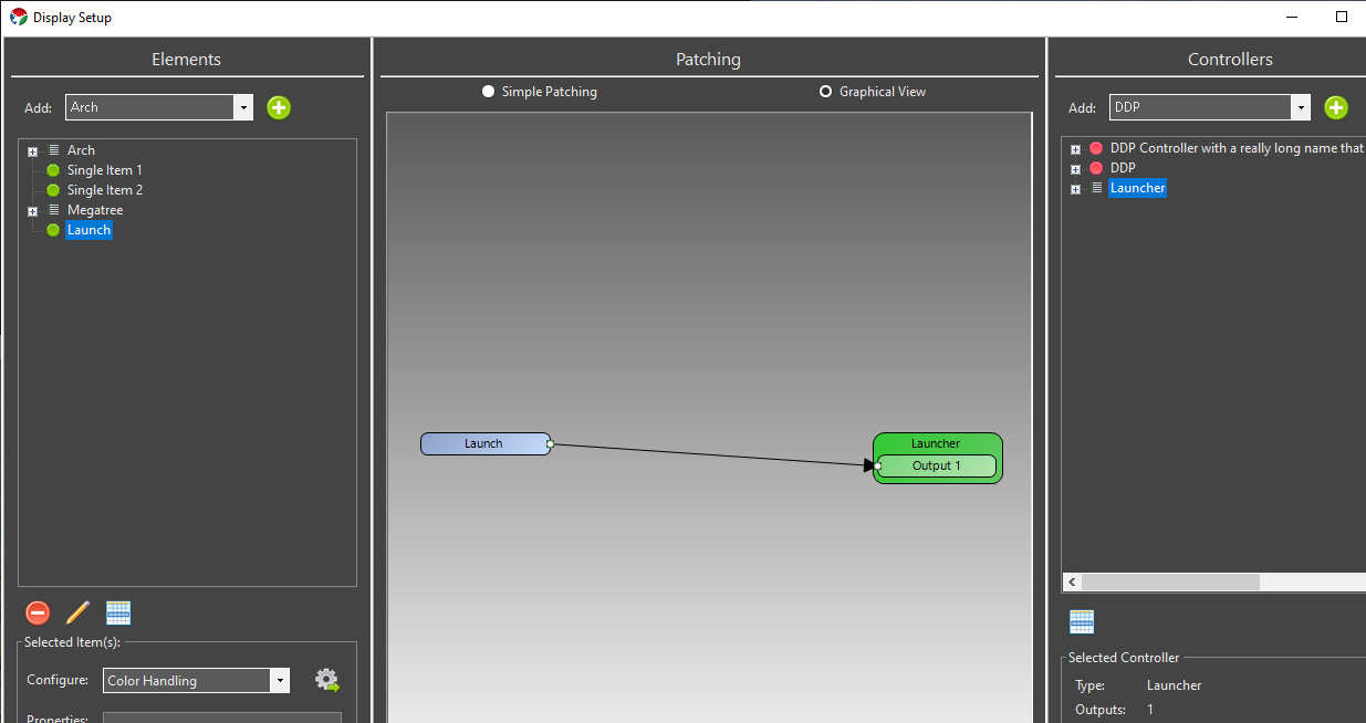
A single Element is normally directly patched to this controller. There should be no color breakdown or dimming handlers in the path. It should resemble the following.
3 - RDS
Description
The RDS Controller is used for triggering RDS (Radio Data System) data over a serial port to one of the supported chipsets. It also can be used to trigger some data to be posted to a url as a query parameter. That could be an RDS controller that supports web requests, or any other endpoint that may or may not be an RDS controller. It is used in combination with the RDS Effect that passes the text through to this controller at a specified time.
Setup
There is minimal setup for this controller if your RDS device has one of the supported chipsets. Just add it to your controller list with one output and ensure it is enabled. Using the gear icon, open the setup screen and select the proper chipset for your RDS controller. The supported chipsets are MRDS192, MRDS1322, or V-FMT212R. The latter being the once popular VAST transmitter. For the MRDS based controllers, select your COM port in the drop down box. There are options for bidirectional and slow which may help with certain serial port setups.
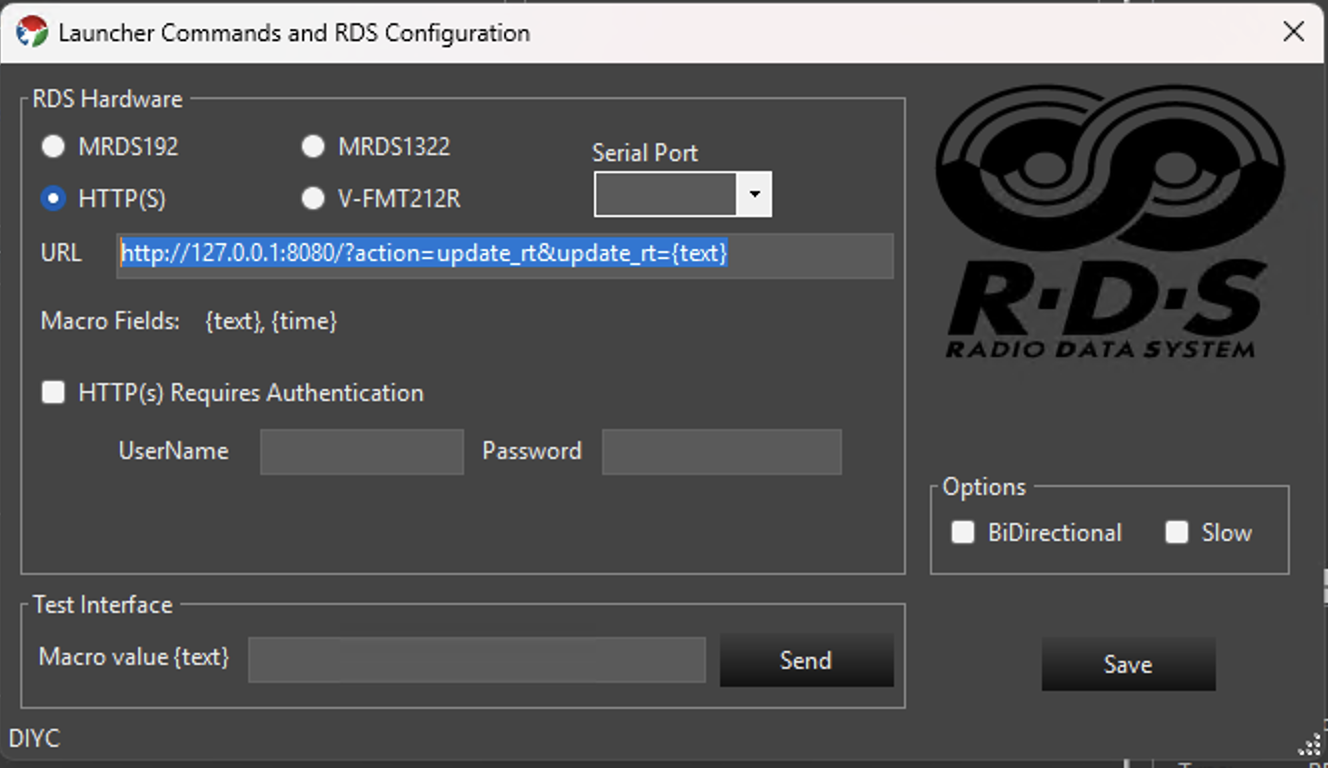
If you are using it for an HTTP controller, or some alternative device that accepts HTTP requests, select that option. You will enter the url in the URL text box. The text parameter from the effect will be used as a query string where you place the {text} macro. The following example calls an endpoint on localhost port 8080 with two query string parameters. The update_rt value will be set to the text from the RDS effect. That specific URL is typical of the VAST device, so if you are using something else, you will need to adjust how the url is configured to match your device.
http://127.0.0.1:8080/?action=update_rt&update_rt={text}
The following shows an example of an HTTP setup without authentication.
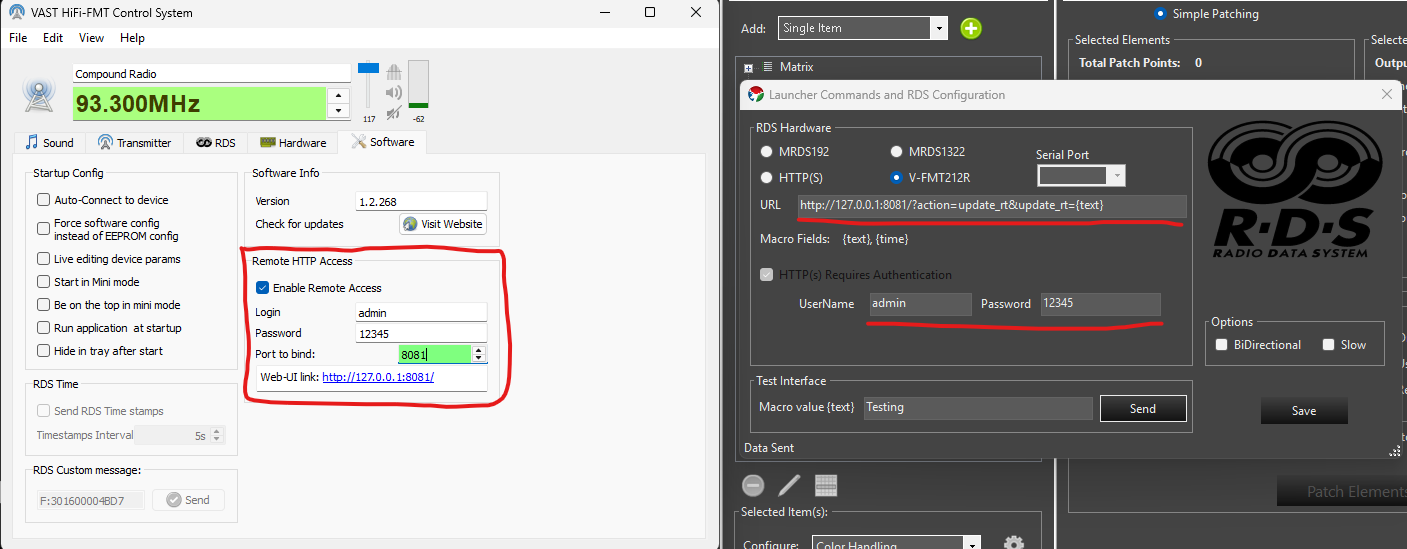
For the VAST V-FMT212R you need to ensure the VAST Control System software is running and has the Remote HTTP Access enabled. Full configuration is shown below. Note the areas highlighted with red. The Vixen web server defaults to using port 8080, so it is recommended to change the VAST port to 8081 as noted in the image.
Testing
You can enter text in the Test Interface section to simulate the macro value being set to some value. This should trigger the integration. On the controller setup page at the bottom is a text box. Entering some text there and hitting send will simulate what will occur if an effect passed the same text value. Your test text will be sent out as it is configured in order to validate your configuration works.
Patching
A single Element is normally directly patched to this controller. There should be no color breakdown or dimming handlers in the path. It should resemble the following. This example shows the Launcher controller, but the RDS controller will look the same.
4 - SanDevices 682
Overview
NOTE some of the screenshots in this tutorial are slightly outdated. The underlying concepts however are sound and this article will remain available until we are able to update it.
If you only have a few strands that you would like to set up in Vixen, or want to get started quickly, setting up one strand per Universe will be the simplest way to achieve this.
In this example I will set up 3 strands of 54 RGB pixels each, running over WS2811.
Since we need 3 channels to drive each of the Red, Green and Blue channels, this means we need:
54 pixels x 3 colors = 162 channels per strand.
162 channels x 3 strands = 486 channels overall.
This example sets it up so that strand 1 is on Universe 1, strand 2 is on Universe 2 and strand 3 on Universe 3.
NOTE: One Universe-per-strand is not a good layout to deal with large displays like Megatrees, and in fact it’s not possible to set up a E682 with 1 Universe per strand and still use all 16 outputs. However, it’s a good way to learn initially, and fine for small displays.
Caveat: This assumes you have nothing else set up. If you do - you will have to change your numbering accordingly.
Configuration Steps
Start by opening your web browser and connect to the SanDevices IP address. It will display the SanDevices configuration page (in this case for a E682):
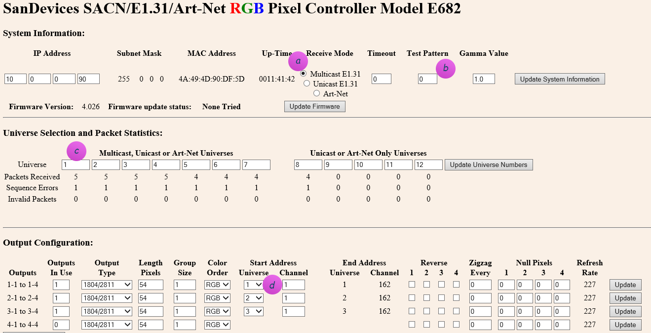
Set the page up as above.
a) Make sure you’ve specified Multicast, and no test pattern.
b) If you change either of those, click Update System Information before proceeding.
c) Make sure your Universe selection contains universe 1 to 12. These are the universes that will appear in the dropdown at (d)
TIP: After you change any one line on the page, you have to first click the button on the right of the line to apply. Don’t fill it all out and then click one of the buttons, you’ll lose all of your other changes!
Connecting to Vixen 3
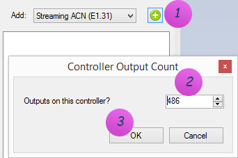
b) To connect the SanDevices controller, in Vixen 3, click on Setup Display and add a new Streaming ACN (E1.31) controller. Specify 486 outputs in order to match the 486 channels (54 pixels x 3 colors x 3 strands).
c) Right-click on the newly added controller, and click on Configure. Add 3 Universes and use Multicast Ethernet, since your SanDevices controller (above) is set up as Multicast E1.31:
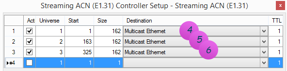
NOTE 1: The name Multicast Ethernet may be called something else. This is the default name on Windows 8. On earlier operating systems it may be called: Multicast Local Area Connection.
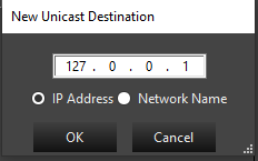
To instead enter a Unicast address, right-click the destination field to bring up the IP address form and enter the ip address, or the host name if you have DNS:
NOTE 3: The Start column above is the Vixen 3 start address of the channel inside its logical E1.31 controller view, and only comes into play if you need to individually map pixels to specific channels. It has nothing to do with the SanDevices controller, and likely will not map to any number you will see on the SanDevices configuration page.
Typically you would just set this up as a contiguous sequence throughout by setting line 1 to start at 1, and for all other lines use the formula of:
Start = Previous line Start + Previous line Size
d) Now create 3 elements to map to the 3 strings. These are the items that appear in the Sequence editor that you will use later to choreograph against.
On the left hand side, add a Generic Numbered Group for String 1. See Setup Display Elements for more information.
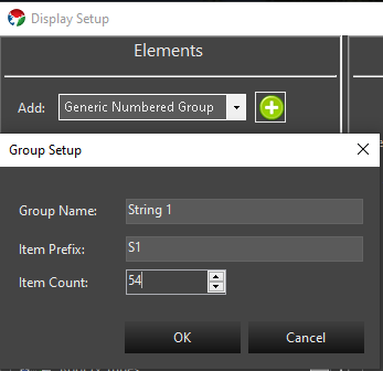
Repeat the same steps for String 2 (item prefix: S2), and String 3 (item prefix: S3).
e) After this you should see 3 strings. Select them all.
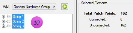
f) Notice above how it says: 162 patch points. At this point Vixen thinks you want 1 channel per item on the string. This is not quite right yet - you instead want 3 channels per item (RGB). So we need to tell that to Vixen. At the bottom on Configure, select Color Handling, and add the RGB filter.
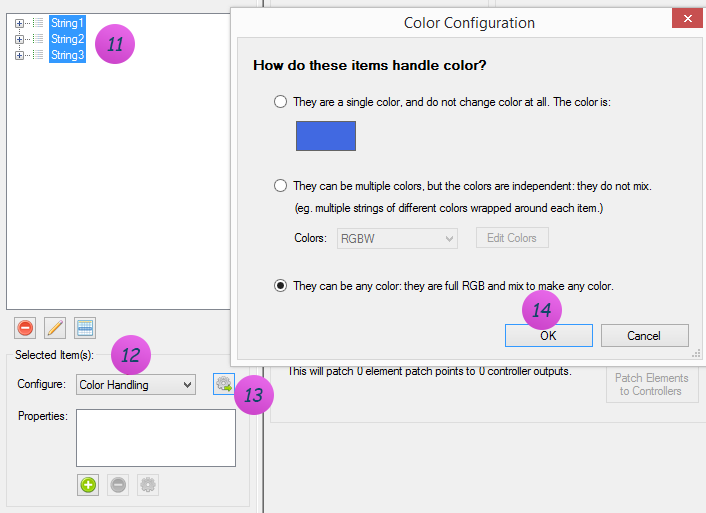
g) If all went well, you should now see 486 patch points on the left, and 486 outputs on the right to path it to:

h) Click Patch Elements in the bottom center section, and you’re off to the races! See Patching Controllers for more information on patching.

5 - Streaming ACN (E1.31)
Description
The Streaming ACN controller, commonly known as E1.31 or sACN, is used to send DMX512 lighting data over an Ethernet network using the ANSI E1.31 protocol. It’s one of the most widely supported protocols in the lighting world; nearly every modern pixel controller (Falcon, SanDevices, J1Sys, ESPixelStick, WLED, FPP based controllers, and many others) can receive E1.31.
Unlike simpler protocols such as DDP, E1.31 is built around the concept of universes. A universe is a block of up to 512 DMX channels (slots) that is addressed and transmitted independently. A single E1.31 controller in Vixen can be configured with as many universes as you need, each mapped to a different range of the controller’s output channels. This makes E1.31 well suited to large displays where your channel count exceeds the 512 channel limit of a single DMX universe - you simply add more universes rather than more controllers.
All of the universes configured on one E1.31 controller instance in Vixen are sent to a single destination - either Multicast (sent out a chosen network adapter, with each universe automatically going to its own multicast group per the E1.31 spec) or Unicast (sent directly to one IP address or hostname). If you need to send data to more than one physical destination, add a separate E1.31 controller for each destination.
Setup
When you add a Streaming ACN (E1.31) controller in Vixen, you’ll be prompted for the number of output channels, just like other controllers. Set this to the total number of channels across all the universes you plan to configure.
Right-click the controller and choose Configure to open the setup screen. It’s split into two tabs: Universes and Advanced Options.
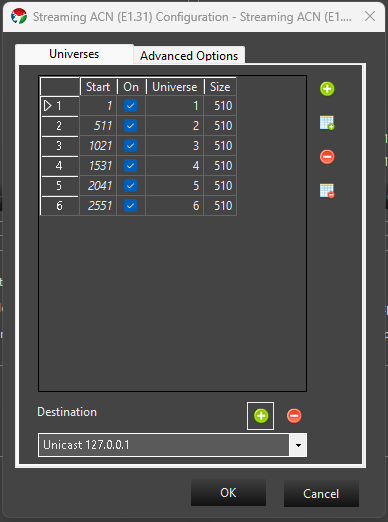
Universes tab
The grid lists each universe configured on this controller:
- Start - the first output channel (1-based) in this Vixen controller that this universe’s data is read from.
- On - whether the universe is active. Inactive universes are kept in the list but not transmitted.
- Universe - the E1.31 universe number, from 1 to 64000. Universe numbers must be unique within a controller.
- Size - the number of channels (slots) in this universe, from 1 to 512.
By default, Vixen automatically manages the Start column for you, laying universes out contiguously one after another as you add or resize them. If you need to control the start channel of each universe yourself - for example to leave gaps, or to match a specific order used by your hardware - check Manually manage start values on the Advanced Options tab. While automatic management is on, you can also click a column header to sort the grid (left-click for ascending, right-click for descending).
Use the buttons to the right of the grid to:
- Add Universe - add a single new universe, numbered one higher than the highest universe currently in the list.
- Add Multiple Universes - add a run of sequential universes in one step; you’ll be prompted for how many to add.
- Delete Universe - remove the currently selected universe(s).
- Delete All Universes - clear the list and start over with a single default universe.
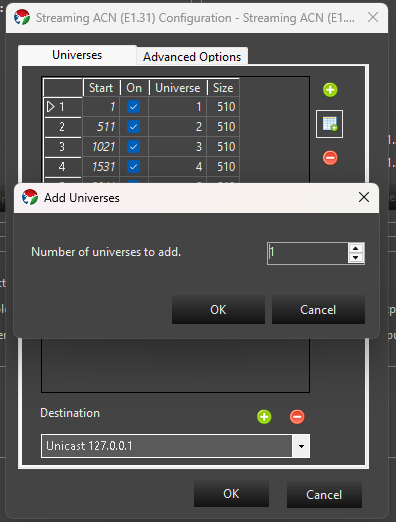
At the bottom of the tab, the Destination drop-down selects where this controller’s E1.31 data is sent:
- Multicast <adapter name> entries are populated automatically from your machine’s network adapters. Choosing one sends standard E1.31 multicast traffic out that adapter; every device on the network subscribed to a given universe’s multicast group will receive it. Multicast destinations can’t be removed since they come from your machine’s network configuration.
- Unicast <address> entries send data directly to a single device. Click the + button next to the destination box to add one - you can enter either an IP address or a network/host name.
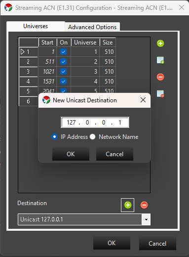
A unicast entry can be removed with the - button, as long as it isn’t currently selected as the destination for another E1.31 controller instance in your setup.
Advanced Options tab
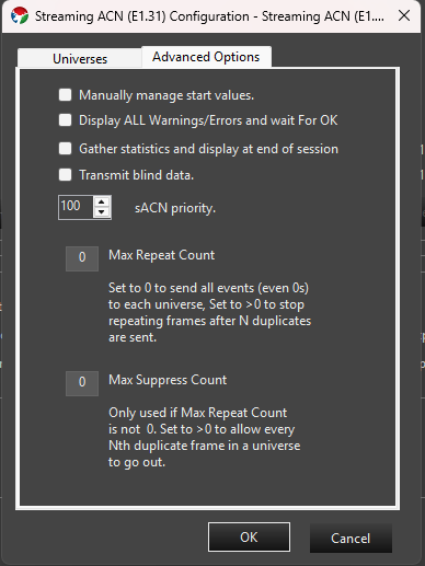
- Manually manage start values - see the Universes tab description above.
- Display ALL Warnings/Errors and wait for OK - if checked, any warnings encountered when the controller starts (for example, a configured network adapter that no longer has an address) are shown in a dialog that must be dismissed before playback continues. When unchecked, these are silently ignored.
- Gather statistics and display at end of session - if checked, Vixen tracks the number of packets and slots sent per universe and shows a summary when the show stops.
- Transmit blind data - sets the Preview_Data flag defined by the E1.31 specification on outgoing packets, marking them as not intended for permanent effect.
- sACN priority - the E1.31 source priority (0-200, default 100) sent with every packet. This is only relevant if more than one E1.31 source is transmitting to the same universe; receivers that support priority arbitration use it to decide whose data wins.
- Max Repeat Count - by default (0) Vixen sends a packet for every frame of your sequence to every universe, even when the data hasn’t changed since the last frame. Set this above 0 to have Vixen stop re-sending a universe’s data once it has repeated unchanged for that many frames, which can reduce network traffic on large shows.
- Max Suppress Count - only used when Max Repeat Count is above 0. Set above 0 to let every Nth suppressed duplicate frame through anyway, which is useful if a receiver needs a periodic keep-alive packet even while your data isn’t changing.
Patching
Elements / Props are patched to this controller just like any other controller. Select the controller and when you patch, the selected elements will be patched to the next available channels. You can also select a range of channels and patch elements to those directly. See Patching Controllers for more information.