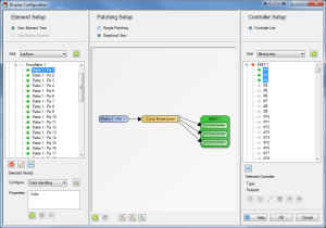
When setting up a light display with Vixen, there are certain configuration steps that must be taken to tell the software what elements and output controllers you will be using. Vixen separates the elements you have in your physical display from the outputs and controllers you use to run your display. You can work all year designing and sequencing a display and setup your outputs as you setup your physical display.
Elements
You can think of an element as an individually controlled item in your display. Examples of a single element is an incandescent or LED string of lights, multiple strings of lights you want to ALWAYS control as a single unit, a single node in an RGB pixel, or even a servo driven prop.
You’ll notice that we call a single pixel an element. In Vixen, all three colors are GROUPED into a single element based on filters (next section) so you can think of this RGB node as a single item. When you sequence this pixel later, you tell it you want it to be blue and it just is.
Standard light strings (single color incandescent or LED strings, multi-color strings, etc.) are what Vixen calls “single color”. There are two ways to configure the color handling of these strings.
Single Color: This is generically what Vixen calls a “standard” string of lights. A single string with all red lights or a single string with multi-colored lights are a both defined as a “single color” item.
Multiple Colors: This selection is used when you have multiple light strings on a single prop in your display that are controlled separately. For example, a popular way to light mini-trees is to wrap them with red, green, blue and white strands of standard light strings but control each of the strings separately. This allows you to set the trees to any one of these colors (or some or all of the colors) at any time in your sequencing. In vixen, you define ONE ELEMENT and tell the software, by selecting this option, that this element is a set of multiple strings of lights. When sequencing, you select an effect and color (red fade for example) and just the red trees light automatically.
RGB strings are defined by choosing this filter. If you have a string of 50 RGB nodes, for example, you would select the string in the element tree and define the color handing as “Full RGB”. This tells each of the 50 nodes that there are 3 colors in EACH of the nodes (150 outputs total).
Controllers
Controllers define single outputs to your physical display. So, for example, if you have an element that is a single color string of lights, this string would be linked to an individual controller. As another example, if you had defined a string with 50 RGB pixel nodes and defined their color handling as RGB, you would link each of these elements to 3 output channels. Your 50 pixel RGB string would be linked to 150 output channels.
Information about setting up DMX intelligent fixture display elements.
Required Materials
Vixen’s support for intelligent fixtures (DMX moving heads) is based on giving Vixen detailed knowledge about your hardware.
To perform this data entry you are going to need the User manual for your fixture that lists the functions your fixture supports and what channel(s) are associated with those functions.
Time Commitment
Expect to spend ~20 minutes defining your fixture profile.
Background
The Intelligent Fixture Wizard has two purposes:
It creates fixture profiles. The fixture profile contains what functions the fixture supports and what channels are used for those functions.
It creates Intelligent Fixture display elements and adds them to the display.
How to Start
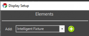
The Intelligent Fixture Wizard can be activated from the Display Setup. Select Intelligent Fixture from the Elements drop down and then select the Plus button.
Video Tutorials
1.1.1 - Select Profile
Information about selecting or creating a DMX intelligent fixture profile.
Select Profile Options
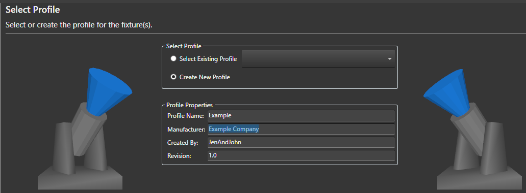
Select Existing Profile - If you have already created a Profile for your fixture you could select it here. The drop down shows all fixtures installed into the active Vixen profile. The fixture profiles are stored within the Vixen profile.
Note in the future users may be able to download fixture profiles from the Vixen website that other users have submitted.
Create New Profile - The default is to create a new fixture profile. The fixture profiles are stored within your overall Vixen profile.
Profile Properties
Profile Name - Name of the intelligent fixture profile. For new fixture enter a unique name. This name is used as the fixture profile filename.
Manufacturer - Optional name of the manufacturer of the fixture hardware.
Created By - This read-only field is determined by the Windows login name.
Revision - Field for keeping track of updates to the profile definition. Refer to Persistance Note below for implications of updating a profile.
If the profile is being updated consider incrementing the Revision number.
Persistance Note
If the Profile Name is changed it is effectively as ‘Save As’’ like operation as the existing profile is not modified.
If anything is changed in a profile, only newly created fixtures will receive the changes.
Existing fixtures are NOT impacted by the changes and if desired will need to be updated via their Intelligent Fixture property.
Select the Next button to continue to configure your intelligent fixture.
Video Tutorials
1.1.2 - Edit Functions
Information about editing intelligent fixture functions.
Background
This wizard page (Edit Functions) and the Edit Channels wizard page define the majority of the fixture.
Vixen comes with a number of built in functions to make this data entry task easier.
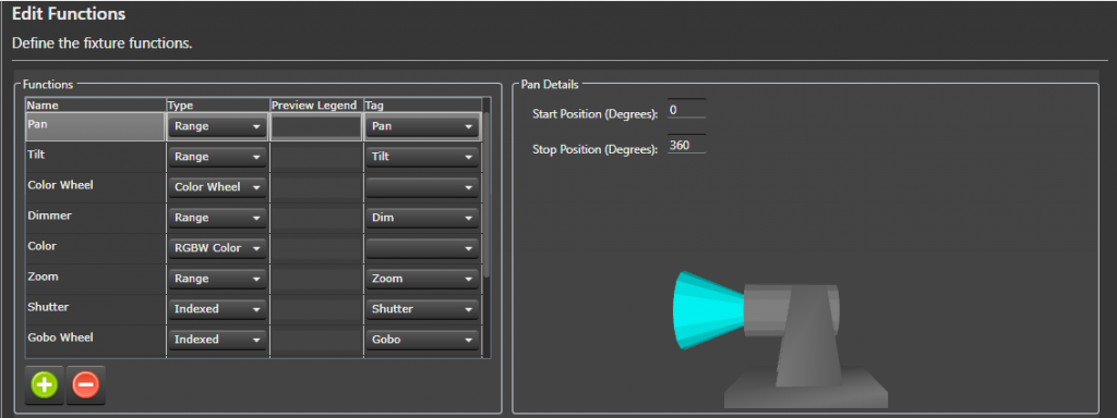
This page defines the functions that will be assigned to channels on the next wizard page (Edit Channels).
The name of each function needs to be unique.
Note the names of the predefined functions can be changed to better match your fixture’s user manual.
What is a Tag?
The Vixen Intelligent Fixture support was designed to allow users to input their fixture channel map information in verbatim.
There are areas of the Vixen Intelligent Fixture support where Vixen needs to know what certain fixture function do.
These areas include the Preview, Effects and automating the handling of certain functions like shutter.
The Fixture Profile uses a tag to give the software the necessary knowledge about the functions.
There is tagging at the function level but there is also tagging for index values.
Many of the built in functions are already assigned a tag.
What Do I Do On This Wizard Page?
Look over your fixture user manual and make sure all your fixture functions are defined on this page.
Note is possible to navigate back and forth between the Edit Functions and Edit Channels wizard pages if you find you need to add an additional function.
Select the Plus button to add additional fixture functions.
Some of the functions require additional details which appear in the details pane to the right.
Create New Function
Select the Plus button to add a new function.
Give the function a unique name.
Assign the function a type (Range, Indexed, Color Wheel, RGB Color, RGBW Color, None).
(Optionally) assign a Preview Legend.
The preview legend is displayed below the fixture with corresponding DMX value assigned to the channel.
This feature can be useful for debugging problems.
Optionally assign a Tag to the function.
See ‘What is a Tag’’ section above for more information.
Assigning Function Details
There are twelve built in functions.
The following sections describe each built in function and what configuration is still required.
The functions in the fixture profile are NOT ordered. If your fixture does not support one of these
built in functions there is no harm in leaving them in the profile. If there is any doubt if a function might
be applicable to your fixture leave it in the list to save data entry. These built-in functions are properly tagged
to maximize support with the Vixen Intelligent Fixture sequencing effects.
Pan Function - Input the range of motion the fixture supports when panning.
This value helps ensure the Preview matches the movement of the actual hardware.
The Start position defines the resting position of the fixture.
The stop position defines the maximum range of movement.
Tilt Function - Input the range of motion the fixture supports when tilting.
This value helps ensure the Preview matches the movement of the actual hardware.
The Start position defines the resting position of the fixture.
The stop position defines the maximum range of movement.
Color Wheel - Defines the colors that the fixture supports.
This function may not be applicable to color mixing fixtures.
Select the Plus button to add a new color wheel entry.
Enter a unique name for the color wheel entry.
Enter the DMX start value for the color.
Enter the DMX stop value for the color.
(Optionally) select if the entry should be controlled via a curve.
Example: select Use Curve when the manual shows a range of DMX values that spin the color wheel.
(Optionally) select the Half Stop option if the entry is half way between two colors on the color wheel.
Note the colors will automatically populated for this entry.
Select the … button to assign the color.
Select the Exclude Color Property option to exclude the color entry from the color property associated with the element.
This option should be selected for colors like CTB and UV.
Zoom Function - Indicate whether the fixture zooms from a narrow beam to a wide beam or vice-versa.
Shutter Function - Defines a function for controlling the fixture’s shutter position.
Select the Plus button to add a new index entry.
Enter a unique name for the index entry.
Optionally select Use Curve for entries that define a strobing rate.
Enter the DMX start value for the index entry.
Enter the DMX stop value for the index entry.
Tag the entry if the entry open or closes the shutter.
This tagging allows Vixen to automatically control the shutter when color is applied to the fixture.
Gobo Function - Defines a function for selecting gobos.
Select the Plus button to add a new gobo entry.
Enter a unique name for the gobo entry.
Optionally select the Use Curve for entries that spin the gobo wheel or define a range where the user should select a specific value.
Enter the DMX start value for the gobo entry.
Enter the DMX stop value for the gobo entry.
Optionally select an Image for the gobo entry.
The image is displayed on the timeline for Gobo effect.
Gobo images are stored in the Vixen profile at \Fixtures\Images.
Select the Import Gobo Images button to copy images to this folder.
Open Close Prism Function - This fixture function may not be mainstream but is similar to a shutter function in that it applies a prism or removes the prism.
For fixtures that support this function it is typical to have one index entry that applies the prism and another entry to remove the prism.
If the entries are tagged Vixen will automatically apply the prism if a prism is selected via another function.
The entry that applies the prism should be tagged Prism Open.
The entry that remove the prism should be tagged Prism Close.
Associated Prism Function - This drop down allows the user to select the associated Prism function that is being opened and closed.
This field is critical when the fixture contains more than one prism function that can be opened and closed.
Prism Function - Defines a function for placing a prism into the beam of light.
Select the Plus button to add a new prism entry.
Optionally select the Use Curve for entries define a range where the user should select a specific value within that range.
This entry will be edited using a curve in effects.
Enter the DMX start value for the prism entry.
Enter the DMX stop value for the prism entry.
Set the Tag to Prism for prism entries that should be available in the Prism effect.
Entries like a Stop can be omitted.
Frost Function - Defines a function that places a frost lens in the beam of light.
This function is a range function and does require any further configuration.
Select the Next button to continue to configure your intelligent fixture.
Video Tutorials
1.1.3 - Edit Channels
Information about editing channels associated with the intelligent fixture.
Background
The Edit Channels wizard page defines the channels on the fixture.
The channels in this grid are order dependent.
When complete the channels in this grid should match your fixture’s user manual.
The number of channels in this grid should match your fixture’s user manual.
Often intelligent fixtures define channels for the convenience of controlling the fixture from a lighting controller with sliders.
If there are channels that are not needed when controlling the fixture from Vixen they can be skipped by placing an Ignore row and a function of None.
A channel with a function of None will be ignored by Vixen. Including these ignore rows are important to keep patching to a controller easy and straightforward.
What Do I Do On This Wizard Page?
This wizard page defines the channels that make up the fixture.
This table should match your user manual precisely.
Channels should not skipped or omitted.
Order is important and should match your fixture’s manual.
Select the Plus button to add a new channel.
Give the channel a unique name.
Select the fixture Function for the channel.
You can use the Wizard Back button to add or edit the functions.
Select the Next button to continue to configure your intelligent fixture.
Video Tutorials
1.1.4 - Color Support
Information about selecting color support for the intelligent fixture.
Background
Vixen will examine fixture channels and functions and default the color support.
This selection is hardware dependent.
The Color Wheel option requires that the fixture has a Color Wheel function.
Vixen will extract all the colors from the color wheel and create a color property for the fixture element with a discrete color for each color on the color wheel.
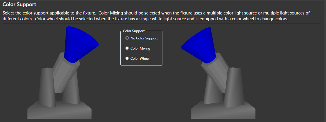
No Color Support - This option can be selected if you want to manually control the color through separate display elements.
This option is not recommended.
Color Mixing - This option should be selected when the fixture uses multiple color sources or multiple light sources of different colors.
Examples are RGB and RGBW.
Color Wheel - This option should be selected when the fixture has a single white light source and is equipped with a color wheel to change colors.
Select the Next button to continue to configure your intelligent fixture.
Video Tutorials
1.1.5 - Automation
Information about configuring intelligent fixture automation options.
Background
This wizard page configures Vixen Intelligent Fixture automation. The goal of the automation is to make it as easy as possible to sequence the intelligent fixture.
Vixen will examine the fixture’s channels and functions and default these options accordingly.
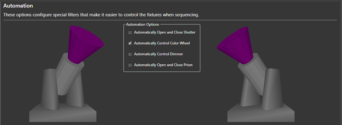
Automatically Open and Close Shutter - This option will automatically control the shutter channel based on the color channels. Whenever an effect is generating color, the shutter will open. Whenever there is no effect, or the effect is dark, the shutter will be closed.
Automatically Control Color Wheel -This option will automatically control the color wheel by matching colors generated in the effects to colors supported on the color wheel.
Automatically Control Dimmer - This option is usually selected for fixtures with a color wheel and fixed white light source. It will automatically control the fixture’s dimmer channel based on the intensity of the colors in the effects.
Automatically Open and Close Prism - This option is usually selected for fixtures that have both a channel for enabling the prism and another channel for selecting the position or movement of the prism.
Select the Next button to continue to configure your intelligent fixture.
Video Tutorials
1.1.6 - Dimming Curves
Information about optionally configuring dimming curves for the intelligent fixture light outputs.
Background
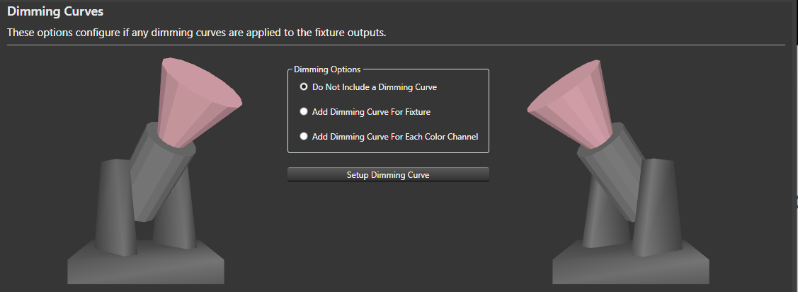
This wizard page configures optional dimming curves for the fixture outputs.
From this wizard one dimming curve can be configured via the Setup Dimming Curve button.
A dimming curve can be useful if you want to ensure you drive the fixture at less than maximum intensity.
Typically used on fixtures with a LED light source.
Do Not Include a Dimming Curve - The default option is not not include any dimming curves.
Add Dimming Curve For Fixture - This option adds a single dimming curve for all color channels.
Add Dimming Curve for Each Color Channel - This option configures a separate dimming curve for each color channel.
With this option all the dimming curves are initially identical.
The curves can be further adjusted via the Patching Graphical View.
Select the Next button to continue to configure your intelligent fixture.
Video Tutorials
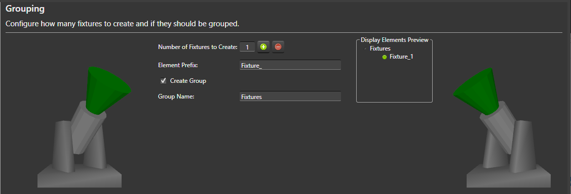
1.1.7 - Grouping
Information about controlling how many fixtures are created and if they are grouped.
Background
This wizard page determines how many fixture display elements to create and if to group them.
This wizard page also determines the naming convention for the fixtures.
The Display Elements Preview to the right gives an indication of how the fixtures will be displayed in the Elements tree.
Note Vixen will modify the element names as necessary to avoid duplicates as all display elements must have unique names.
Number of Fixtures to Create - Number of fixture display elements to create.
Select the Plus button to have the wizard create additional fixtures.
Element Prefix - Name prefix for the fixture display elements.
Create Group - Determines if the fixtures are nested under a group in the display element tree.
Group Name - Name of the fixture group.
Select the Next button to continue to configure your intelligent fixture.
Video Tutorials
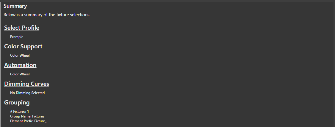
1.1.8 - Summary
Summary information about the intelligent fixtures about to be created.
Background
The Summary wizard page summarizes the selections made on the previous pages for review.
Select the Finish button for the wizard to actually create the fixture display elements and save the fixture profile to the file system.
1.2 - Setup Display Elements
Concepts
Elements are the main building blocks of your display. Every display item you want to use in your show will need either an element, or an element group defined for it.
Adding Single-Element Items
An item such as a single string of lights is defined as a single item in the Element Tree. So, if you have a string of lights that is a single color, or even a single multi-colored standard string, it is defined as a single element. Think of if this way. If you plug it in and can only control the entire string at once, it is a single display item. Conversely, if you can set each light to any number of colors or there are is more than one controllable item in the string, it is not defined this way.
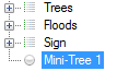
Right-click somewhere in the white-space of the Element Tree and select Add.
Give your element a name. We’ll call ours Mini-Tree 1. The new element will be added to the list as a single node.
Click on the newly created element to select it.
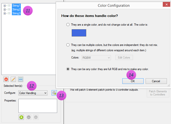
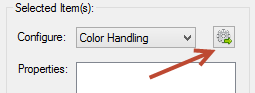
Make sure Color Handling is selected in the Selected Item(s)/Configure section and press the Configure button
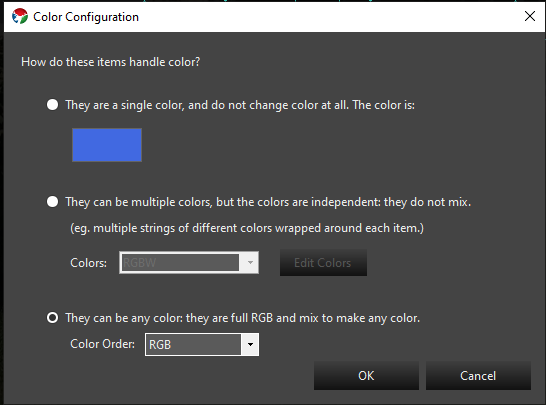
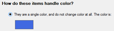
When the Color Configuration dialog box appears, click on the first radio button (They are a single color…).
Click the color box (blue in the above graphic) to define the color of this element.
Click OK when you’re done and you’ll get a dialog box telling you what you just did – hit OK on this dialog to close it.
That’s it. You’ve successfully defined a single element for your display.
There is no need yet to link anything in the Element Tree to output controllers. With these elements defined, you can sequence your display and setup a preview. Only when you are ready to physically connect your output controllers do you need to come back and mess with the controllers.
Single-Element Shortcuts
Let’s say you have 16 mini-trees that are a single color (mine are white). These are standard 120V light strings and each is separately controlled by a channel on a Renard controller (so, 16 strings, 16 outputs on a controller)
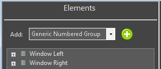
Select Generic Numbered Group from the Add combo-box under Element Setup.
Click on the to the right of Generic Numbered Group drop down box.
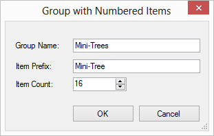
A dialog box will appear that lets you name your new element group and each item within the group. We’re going to fill ours out with a group name of Mini-Trees, an item prefix of Mini-Tree and an item count of 16.
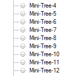
When you press OK a new group will be created at the bottom of the Element Tree named Mini-Trees with 16 individual trees named Mini-Tree-X where X is the number of the item.
Now, we need to define the color-handling for these items. For versions 3.6 and above the following steps will be invoked automatically for you when you create an item with the prop shortcuts. In addition, you will be prompted to ask if you need a dimming curve to control the brightness of your prop. Click on the Mini-Trees group so it is selected.
Make sure Color Handling is selected in the Selected Item(s)/Configure section and press the .
When the Color Configuration dialog box appears, click on the first radio button (They are a single color).
Click the color box (blue in the above graphic) to define the color of this element.
Click OK when you’re done and you’ll get a dialog box telling you what you just did — hit OK on this dialog to close it.
That’s it. You’ve successfully defined a group of single 16 elements for your display.
Multiple-Element Shortcuts
1.3 - Renaming Elements
Introduction
There are multiple ways to rename elements. The simplest form is a single item rename. There are also features that enable multiple items to be renamed at the same time. One of them will be discussed here. The other one has it’s own section under Find/Replace.
Simple Renaming
To rename a single element, you can select the element and then right click and select rename. You will be prompted with a dialog to enter the new name. Clicking the ok button will apply the change. If the new name for the element matches an existing name, it may append a unique qualifier because all element names must be unique.
Multiple Element Rename
When you select multiple items to rename, a dialog box will appear to allow you to shape the renaming by forming templates. These templates are the same as the one used in the Add Multiple helpers that generate elements based on sequential naming patterns.
1.4 - Renaming Elements by Find/Replace
Introduction
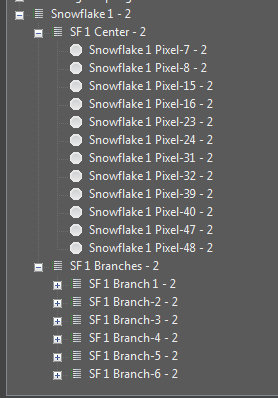
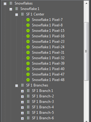
You may have element structures that were created with names that did not have the exact structure you wanted or have evolved over time and need some restructuring. The standard rename function has abilities to rename multiple items via a sequential template format. At times, this may be too rigid for your needs and a simple find replace mechanism can better serve the purpose. An example is shown below where the paste as new function was used to duplicate a element group structure. The groupings themselves have elements that have been restructured out of a sequential naming structure. The intent here is to remove the - 2 on the end and change it from Snowflake 1 to Snowflake 5. This way the newly cloned element group will match the pattern of the original ones it was cloned from. See element duplication for additional details. Starting in 3.6 and above this can be done from the Display Setup or the Preview Setup forms.
Steps
Select a group of elements to Find/Replace naming patterns. They can be all together, or slected from multiple different levels. Select only the items you wish to act on.
Right click on the selected items and choose Find/Replace.
On the dialog box that appears you can create patterns of find and replace. Patterns can be chained to allow for multiple find replace operations in one pass without having to do the Find/Replace operation multiple times.
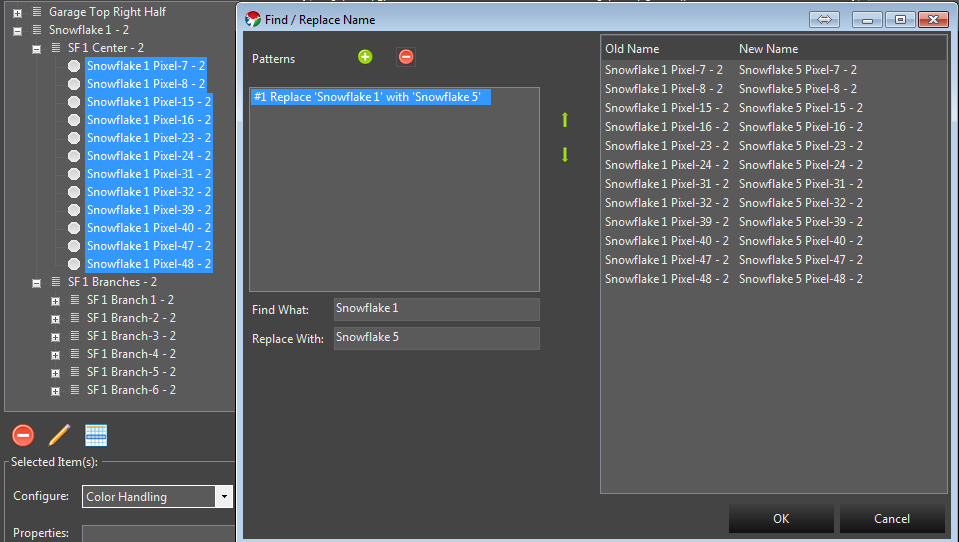
First we will create the pattern to rename Snowflake 1 to Snowflake 5. In the Find what text field we put Snowflake 1. In the Replace with text field we put Snowflake 5. You will notice the list at the left showing on the fly what will happen as you type the values in.
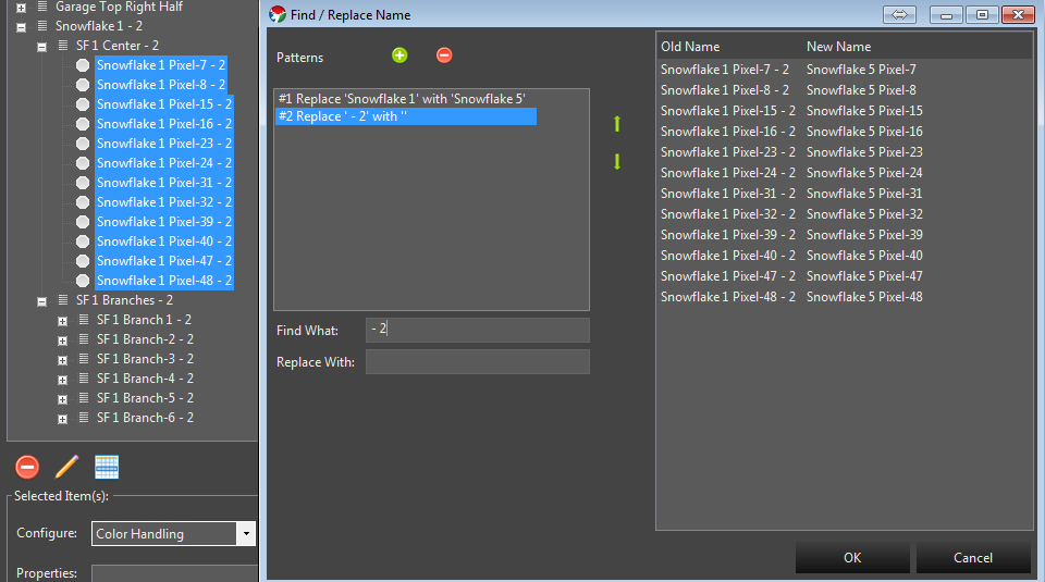
Next we also want to remove the - 2 on the end. So we click the green + button to add a new pattern. This new Find/Replace will occur on the result of the previous pattern. We enter a the - 2 in the find what. Notice we enter a blank space in front because we also want to remove the blank that is there. - 2. Because we want to replace that with nothing, we leave the replace with text field empty. The list on the right updates to reflect the result of all our changes.
Now that the list on the right reflects what we want the elements to look like, we can click the ok button and the changes will be applied.
1.5 - Duplicating Elements
Introduction
In some cases you may have created an element structure that does not conform to one of the built in template generators and you need to create more of them. Instead of manually recreating each one, Vixen has a feature to allow you to copy and paste a new version of it. Normally copy and paste just makes additional copies that are linked to the original. But in this case you truly want a new version of it.
Steps
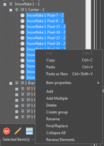
Select the top level of the item group you want to make a new version of. In the example above I would select the Snowflake 1 Element group.
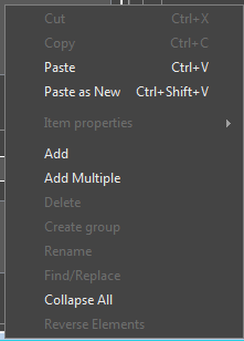
Right click out in the white space area of the element list and the context menu will appear.
Choose Paste as New. After this a cloned copy will be created as shown below.
Because Vixen does not allow different elements to have the same name, the feature will append some numeric qualifier on the end of the new elements to make them different. You can leave these as is, or use some of the renaming features described elsewhere to rename them.
1.6 - Color Handling
Color Handling
Color handling provides information on how the elements use color. There are 3 common types of lights.
Traditional analog incandesent, or LED string lights. These have been around for a long time and are typically a string of single color lights.
Dumb Pixels. These are LED pixels, but the whole string color can be controlled and will all be the same color at the same time. They lights are not individually addressable.
Pixels. These are modern addressable string of lights that can be made any color and each light can be any color.
The color configuration can occur from multiple places. If you add elements in display setup using the templates, the color setup will typically be presented as part of the setup workflow for each type of prop. If you create individual elements outside of one of the wizards, then it will be presented when you use the Add Properties -> Color Handling.
Color Configuration
The Color Configuration dialog will be presented from multiple places. It is key to getting the color setup correct on your elements so the sequencer can properly manage them. There are 3 options on this dialog and they relate to the information above on what type of lights you are using.
Single color. This is for traditional lights where the element is a single color only.
Multiple colors that do not mix. This is for waht is known as super strings of traditional lights. A single prop may have multiple strings of different color lights covering the same area. You would configure this to have the set of colors that match what your strings are.
Mixing color types. This is typical of a pixel that can be any color. Typically they are RGB.
2 - Controller setup
Information about setting up display controllers.
2.1 - Launcher
Description
The Launcher Controller is used for triggering an external command from within Vixen. It is used in combination with the Launcher Effect that passes the command line executable and any arguments through to this controller at a specified time.
Setup
There is minimal setup for this controller. Just add it to your controller list and ensure it is enabled. You typically only need one ouput which is the default.
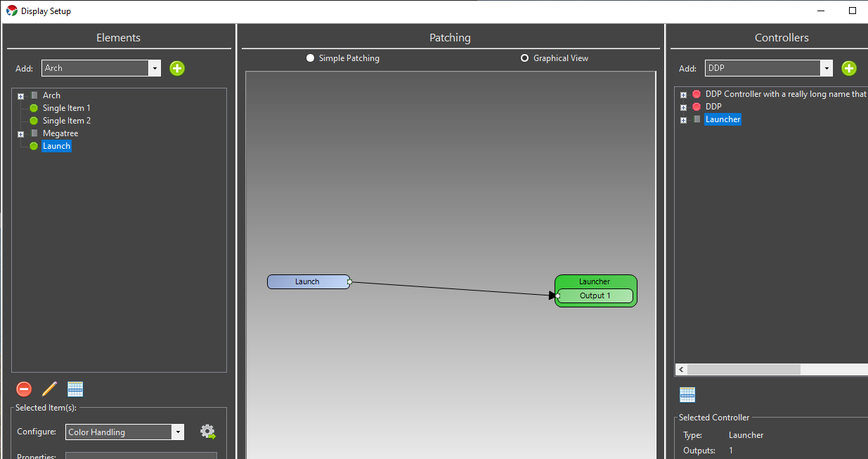
Patching
A single Element is normally directly patched to this controller. There should be no color breakdown or dimming handlers in the path. It should resemble the following.
2.2 - SanDevices 682
**NOTE some of the screenshots in this tutorial are slightly outdated. The underlying concepts however are sound and this article will remain available until we are able to update it.
If you only have a few strands that you would like to set up in Vixen, or want to get started quickly, setting up one strand per Universe will be the simplest way to achieve this.
In this example I will set up 3 strands of 54 RGB pixels each, running over WS2811.
Since we need 3 channels to drive each of the Red, Green and Blue channels, this means we need:
54 pixels x 3 colors = 162 channels per strand.
162 channels x 3 strands = 486 channels overall.
This example sets it up so that strand 1 is on Universe 1, strand 2 is on Universe 2 and strand 3 on Universe 3.
NOTE: One Universe-per-strand is not a good layout to deal with large displays like Megatrees, and in fact it’s not possible to set up a E682 with 1 Universe per strand and still use all 16 outputs. However, it’s a good way to learn initially, and fine for small displays.
Caveat: This assumes you have nothing else set up. If you do - you will have to change your numbering accordingly.
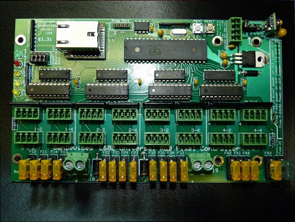
Configuration Steps
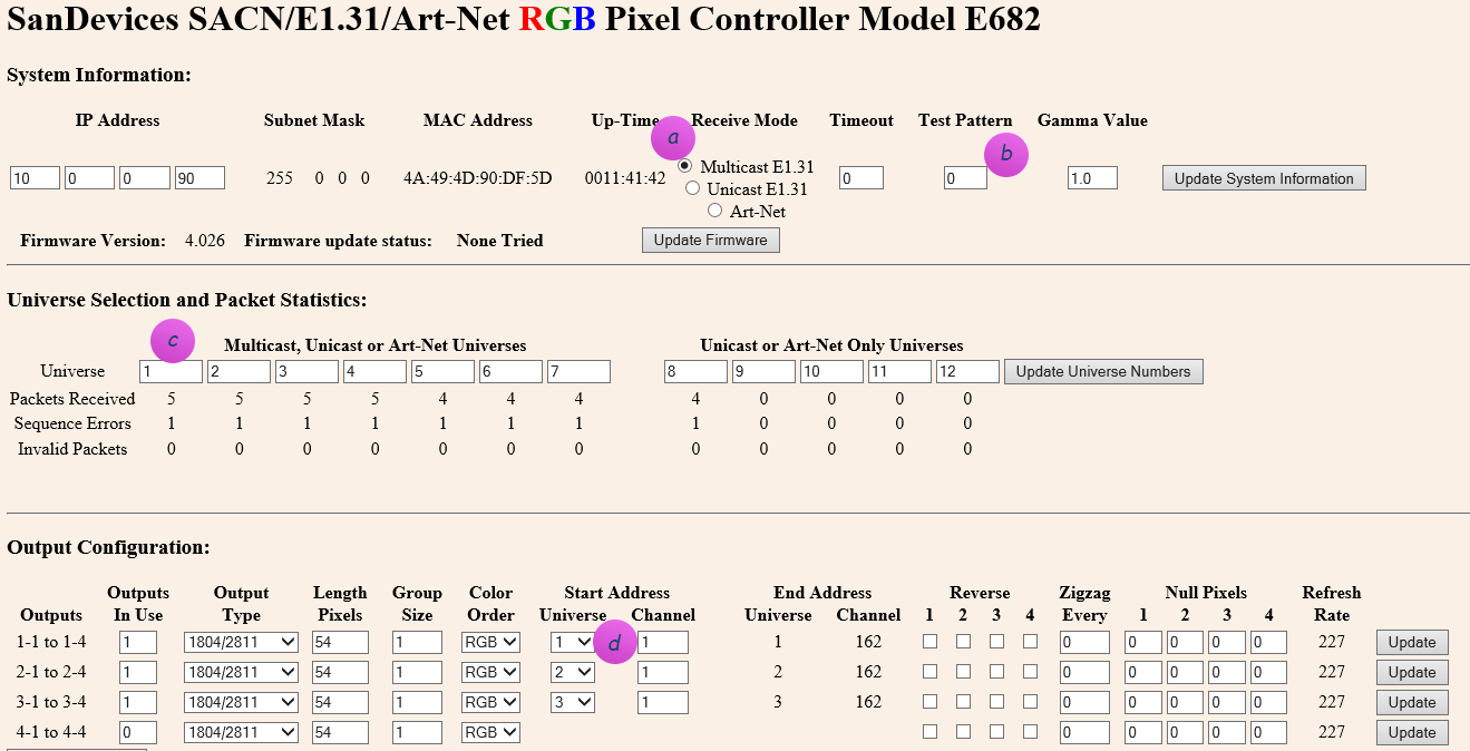
a) Start by opening your web browser and connect to the SanDevices IP address. It will display the SanDevices configuration page (in this case for a E682):
Set the page up as above.
a) Make sure you’ve specified Multicast, and no test pattern (b). If you change either of those, click Update System Information before proceeding.
c) Make sure your Universe selection contains universe 1 to 12. These are the universes that will appear in the dropdown at (d)
TIP: After you change any one line on the page, you have to first click the button on the right of the line to apply. Don’t fill it all out and then click one of the buttons, you’ll lose all of your other changes!
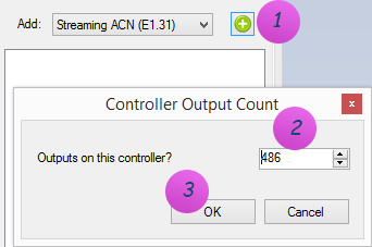
Connecting to Vixen 3
b) To connect the SanDevices controller, in Vixen 3, click on Setup Display and add a new Streaming ACN (E1.31) controller. Specify 486 outputs in order to match the 486 channels (53 pixels x 3 colors x 3 strands).
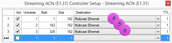
c) Right-click on the newly added controller, and click on Configure. Add 3 Universes and use Multicast Ethernet, since your Sandevices controller (above) is set up as Multicast E1.31:
NOTE 1: The name Multicast Ethernet may be called something else. This is the default name on Windows 8. On earlier operating systems it may be called: Multicast Local Area Connection.
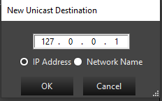
To instead enter a Unicast address, right-click the destination field to bring up the IP address form and enter the ip address, or the host name if you have DNS:
NOTE 3: The Start column above is the Vixen 3 start address of the channel inside its logical E1.31 controller view, and only comes into play if you need to individually map pixels to specific channels. It has nothing to do with the SanDevices controller, and likely will not map to any number you will see on the SanDevices configuration page.
Typically you would just set this up as a contiguous sequence throughout by setting line 1 to start at 1, and for all other lines use the formula of:
Start = Previous line Start + Previous line Size
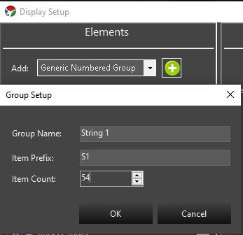
d) Now create 3 elements to map to the 3 strings. These are the items that appear in the Sequence editor that you will use later to choreograph against.
On the left hand side, add a Generic Numbered Group for String 1. See Setup Display Elements for more information.
Repeat the same steps for String 2 (item prefix: S2), and String 3 (item prefix: S3).
e) After this you should see 3 strings. Select them all.
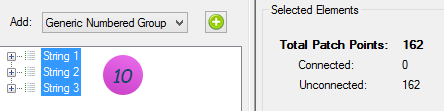
f) Notice above how it says: 162 patch points. At this point Vixen thinks you want 1 channel per item on the string. This is not quite right yet - you instead want 3 channels per item (RGB). So we need to tell that to Vixen. At the bottom on Configure, select Color Handling, and add the RGB filter.
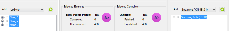
g) If all went well, you should now see 486 patch points on the left, and 486 outputs on the right to path it to:
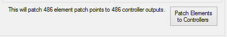
h) Click Patch Elements in the bottom center section, and you’re off to the races! See Patching Controllers for more information on patching.
3 - Patching Setup
Information about patching elements to controllers.
3.1 - Patch Elements to Controllers
Introduction
In order for your controllers to output data, the elements need to be connected to them. This is a process we call Patching Think of the old telephone switchboards where an incoming call needs to be connected by an operator to a destination. The operator plugged in a cable from one jack to another to connect the calls. They called this patching the call. The same concept applies here. This allows your elements to be connected to your controllers in any order providing great flexibility.
The graphical view in the center pane of the Display setup screen shows what’s going on.
In this screenshot you can see that one element is patched to a color breakdown filter which in turn has 3 outputs that route to the controller output channels.
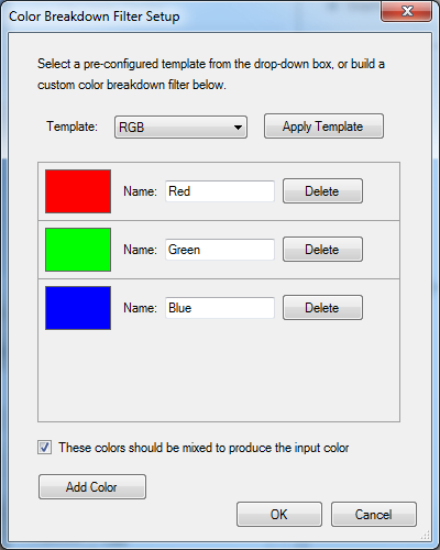
So what’s going on in that color breakdown filter? If we were to double click on it, you’d see the setup screen.
What this is doing is taking the element information, and breaking down the colors to 3 separate paths, one for the red, one for the green, and a 3rd for the blue. Most RGB lights in common use need to get the data for each color on separate control channels. This breaks it up so the controllers can understand it.
From this filter, the data is patched to the appropriate controller channels. Note that should your RGB lights be in a different RGB order, you can change the order of the colors in the color breakdown filter, or you could repatch the outputs of the filter with patching lines that cross. Either way is equally valid.
Filters vs Properties
This can be confusing. Properties are information about the element that are used by various parts of the software. Currently an element can support Color, Grid, or Location properties. The element color properties are used in the sequence editor so that you are only presented the color options for colors that this element supports. Editing the color property does not alter the color breakdown filter. Editing the color breakdown filter (in graphical view) does not alter the color property. The easiest way to change them both, is to unpatch the element, and start over.
Filters affect how the data flows from elements to controllers. They do not “belong to” an element, but rather are independent objects that are connected to elements, other filters, and controller channels.
When you use the configure button to add color handling. This invokes a wizard which sets up both the element’s color property, as well as a color breakdown filter.
Conversely, when you add a dimming curve, the wizard only adds the dimming curve filter, and no properties.
It’s important to note that the list box below the configure button is a list of the properties assigned to an element. Only some configure wizards will produce a property in this list. And even if it has a similar name, the property is not at all linked to a filter.
Patching Process
First you need to make sure your filter chain is the way you want it. Select the element(s) you want to patch from the element setup pane on the right.
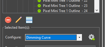
Decide if you want to include dimming curves, and if so, how much control you wish to have over it. If you want to add a dimming curve and have the same curve apply all of the colors add it at this point. (this gives it a dimming curve, but no ability to color balance)
One Dimming curve will be added for each element. Hint: Use a library curve. See Dimming Curves below.
Then go to the configure box below and select color handling.
Choose the appropriate color handling scenario for these elements.
One color breakdown filter will be added for each element.
If you want to add dimming curves to this element that you can adjust with different curves for each color, add the dimming curve at this point. (You would do this if you want to color balance your elements to each other)
One dimming curve will be added for each output of the color breakdown filters (for RGB, number of elements x 3). Hint: Use a library curve. See Dimming Curves below.
Double check the graphical view to make sure this is the signal flow you are trying to achieve. If you’re satisfied, go back to the simple patching view.
Now take note of the number of patch points in the selected elements section of the simple patching view. This is the number of controller channels you’ll need.
Select the controller channels you want to connect these elements to. Note: You can select more channels than needed, and only the necessary channels will be used. It’s faster to select more outputs than necessary than it is to actually count out how many you need.
In the bottom area of the center pane, it will tell you how many element patch points will be connected to how many channels. If the number doesn’t match, that may be ok (see note above) but ideally these numbers should match. If they don’t match, there will be a message below that explains what will happen.
Once you’re satisfied that it’s good, go ahead and hit the Patch Elements to Controllers button.
There may be cases where your physical lights are backwards from how you have your elements set up. You can account for this in the patching process by using the Reverse Element Order option in the Selected Elements column.
There is a similarly worded option in the Selected Controllers column as well. The difference here is that the output channels will be reversed. If this is an element with a multi-output color breakdown filter (such as RGB) not only will the elements be patched in reverse, but the color order will also be reversed. You probably don’t want to use this option to reverse multicolor elements.
Unpatching
If you want to preserve the filter chain, you’ll want to unpatch from the controllers. Select the controller channels to be unpatched, and press the Unpatch Controllers button
If you want to discard the filter chain and recreate it, you can unpatch from the elements. Select the elements to be unpatched, and click the Unpatch Elements button. It will then ask you if you want to remove the filters as well. The answer is almost always yes. (there’s some legacy reasons why you wouldn’t want to remove filters, but you can no longer get to them from the display setup screen, so you might as well delete them)
Dimming Curves
It was mentioned above, but to additionally call it out. The best practice when adding dimming curves to your elements is to use a library curve for the curve when setting it up. This allows you to go into the curve library and edit the library curve to change any instance of the dimming on the elements it was used to patch. We recommend giving it some thought and setting up a library curve for each prop that you may want to adjust or even all items that use the same type of lights so you can easily balance them. Adjusting the library curve values once patched in makes an immediate change to the output. Alternatively, you can choose to just replace the existing curve with a new one in the display setup. You do not have to unpatch to replace an existing curve with a new value, however you will need to restart Vixen to see the results. Thus the library curve has an advantage of being able to change without a restart.
The best place to position the curve in the filter chain is between the element and the color break down in most cases. This allows you to adjust the overall brightness of the light evenly across whichever colors are on the breakdown filter. If you need to adjust color balance, then the place for the curve is after the breakdown on each individual output of the breakdown. In the case of RGB pixels, you most likely want to have a red curve, a blue curve and a green curve in your library for that prop or type of lights. You can then adjust each color in the library to adjust for color balance.
3.2 - Dimming Curves
Dimming Curves
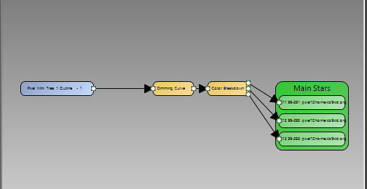
Dimming curves are generally used to reduce the overall brightness of a one or more lights. Generally this is used with RGB pixels. Dimming curves themselves are the very same curves you may be familiar with in the Sequencer for controlling brightness or other aspects of effects. They are utilized in the patching chain to affect the output to the lights. They will not affect the brightness shown in the preview. Here is a typical view of the patching chain for a single RGB pixel in the graphical view of the display setup.
Typical patching with dimming curve.
The dimming curve typically precedes the Color Breakdown filter. This evenly affects all color values flowing through the path. The Dimming Curve wizard helps you add a dimming curve to your patching.
Invoking the Dimming Setup.
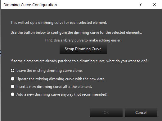
Setup screen.
The main setup screen helps you add the dimming curve. The typical choices here will be to update an existing dimming curve, or insert a new dimming curve after the element. If you are starting your patching, you will use the insert a new dimming curve. This is also true in the newer workflows in the preview when adding a prop or using the wizards and they prompt you to add a dimming curve. These new prop wizards will default to using the insert option. When updating an existing dimming curve, you may need to restart Vixen for it to take effect.
Dimming Curve Setup
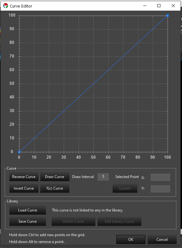
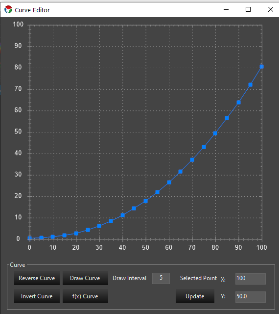
Clicking the Setup Dimming Curve from the Dimming Curve wizard will bring up the curve editor. This editor is used in other places to edit curves so it will become familiar to you. Below is the default curve that will be the starting point.
Default Dimming Curve.
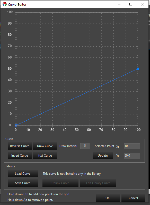
This is a standard linear ramp. It is a mapping transform, so the value across the bottom is mapped to the the value on the left by moving up the graph to the curve line to find the outgoing value. The above curve will produce the same values out that come in and will not do any dimming. If we want our lights to run at 50% brightness, we will configure the curve as follows.
A common misconception is that the curve should be a flat line. A flat line will result in all values being mapped to the same brightness. This is generally not what you want.
Gamma Curves
Pixel based lighting has a linear brightness response. The human eye does not perceive these linear steps as being equal. There are many articles about using a gamma curve to compensate the linear response to something the human eye visualizes better. We can implement gamma curves in our dimming flow to do this compensation. There is a curve generator option in the curve editor to generate a gamma curve for you.
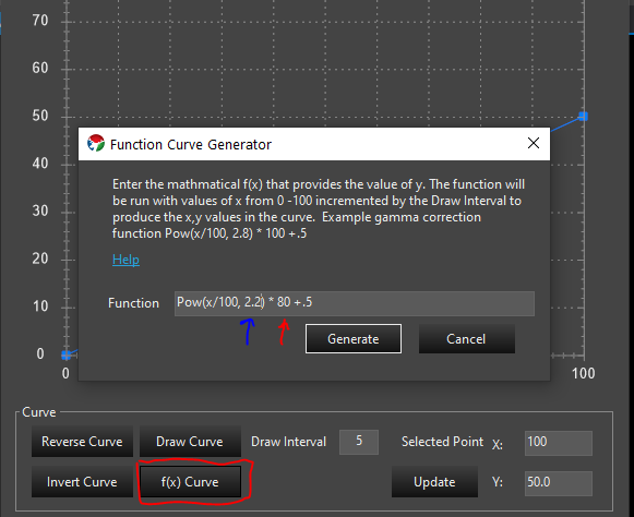
Function Curve Generator.
Using the f(x) Curve button you can invoke a screen to allow you to generate a gamma curve. The formula for a Gamma curve is in the screen. You can copy the example and edit it to your needs. The value indicated by the red pointer is the max brightness. In the example that is 100 and above it has been changed to 80 indicating that the max value for brightness is 80%. The value indicated by the blue arrow is the gamma value. A range of 2.0 – 2.4 is fairly typical. This value can be experimented with to find the value most appealing to the eye. If you happen to have gamma specs for your lights, you can use that value here. Above it has been set to 2.2.
Gamma Curve with 80% max and gamma of 2.2.
The above image is the result of generating the curve with a 80% max brightness and a gamma of 2.2.
Library Curves
The best practice for adding dimming curves is to create the curve as a library curve. This allows you to edit the curve in the library to change the value instead of having to use the Dimming wizard to replace the curve anytime you wish to change the value. On the curve editor you can can save your new curve. This will save it to the library. Once you save the curve you will use the load curve button to load that saved library curve so library version can be used as the dimming curve. If you already have a curve saved you can load it directly and reuse one from other props. Library curves can be edited in the sequence editor in the curve library. Additional information on curves can be found here: Curves
 button to add additional fixture functions.
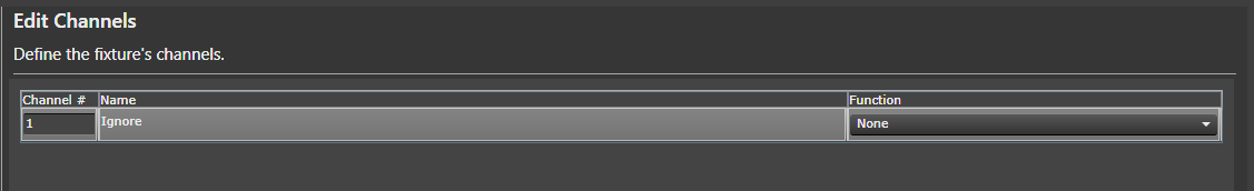


 to the right of Generic Numbered Group drop down box.